Saturday, August 5, 2017

Changing the Ford Triton spark plugs

I could have called this entry "The definitive reason why I don't like fords" or "FoMoCo shit engineering" (but that would be more of a book than a blog post) but instead the title is the title and after reading this you might understand (and in a few cases I have said) that it's not necessarily the vehicle I dislike, but some of the engineering that went into it.  The biggest thing I do not like about the 4.6L, 5.4L, and 6.8L triton engines with three valves per cylinder is that the plugs have a tendency to break off in the cylinder head. The earlier engines with two valves per cylinder have a tendency to spit the plugs out, and take the coil out in the process.

At any rate, to do this job you will need the following tools:
3/8 ratchet, and extensions (3", 6", a 3/8" swivel attachment.)
A 9/16" deepwell socket. You can get a 9/16" spark plug socket but they are hard to find.
A 5/8" socket.
A 3/4" socket, deepwell.
A 3/4" wrench.
A 7/8" socket, deepwell.
Penetrating oil. (I use and recommend PB Blaster)
A 7mm socket.
A 8mm socket.
A magnet and/or a parts grabber.
A pair of needle nose pliers.
A six to eight inch length of 3/8"ID hose
Copper (high temperature) anti-seize.
A kit specifically made for extracting broken plugs from Triton three valve engines. Do NOT attempt this procedure without it.
This is the Ford Triton Engine spark plug removal tool. Don't attempt this procedure without this kit.


I started with the driver's side of the engine for this procedure.


Step one: remove the air intake hose between the front of the truck and the throttle body.

Step two: unbolt and set aside the degas bottle mounted the firewall.

Step three is to remove the line running from the intake to the valve cover.

Step four: Using the 7mm socket, remove the bolt that holds the coil in place. Immediately place the bolt aside where it will not get lost or worse, find it's way into the combustion chamber.

Step five: Grab the top of the coil, and with a twisting motion, pull the coil off of the plug. (These engines use a coil on plug ignition system, meaning there is one coil per plug.) If the rubber boot should happen to stay on the spark plug, use the needle nose pliers to twist the boot and remove it. It should be notes that these coil packs snap together so if the boot is separated from the coil pack housing itself, it's not the end of the world.

Repeat steps four and five for the rest of the coils on this side.

Step six: Spray some penetrating oil into the spark plug recesses. Let it work for a minimum of thirty minutes. Use this time to remove the coils from the passenger side of the engine, then spray the penetrating oil into those plug recesses.

Step seven: Using the 9/16" socket, ratchet and extensions as needed, remove the plugs from the cylinder head. Be warned, these plugs will be very tight. Go slow, take your time.

Step eight (assuming the plug stayed together): if the plug falls out of the socket upon extraction, Use the magnet to snag the top of the spark plug and carefully pull it out of the recess. if the plug was broken off remove the portion of the plug that is loose.

Step nine: If any of the plugs were broken off, use the extraction tool to get the broken pieces out.

Step ten: Now that the plugs are free of the cylinder, apply the copper anti-seize to the plug threads and the area immediately below the threads. Place the hose over the top of the plug, and use the hose to start threading the plug into the cylinder head. This method prevents cross threading.

The copper colored stuff on the plug is high temperature anti-seize. This will go a long way towards keeping the plugs from breaking off in the cylinder head when you do this again. Also note the heater hose on the end of the plug. Once the spark plug is threaded into the cylinder head a couple of turns this hose will twist off of the plug.


The passenger side removal is almost the same as the driver side, with the only real exceptions being some vacuum lines that you can remove to make this job a little bit easier.   Some other things that others have tried to make plug removal easier include:

-Let the engine run long enough to get warm.
-Soak the plugs in the block in penetrating oil overnight.
-run one bottle per tank of seafoam for two tanks of gas to clean the carbon off of the plugs.
-Pay someone to do this for you. (But at around $450.00 that's kind of expensive.)

The plug on the left is the new plug, the one on the right was in the engine way too long, as shown by the worn electrode.

This picture shows where the plug has a tendency to break off. Again, you will not get the broken off piece out of the head without the special kit.
Here are all eight of the plugs out of the engine...I only broke three of them (new personal record).

Sunday, March 12, 2017

Dodge Durango full on seat repair.

It's time for full on seat repair, Dale style!

I am convinced that one of the "elderly parents" of the individual I bought the Durango from weighed in at about six hundred sixty six pounds or so, give or take a king size snickers bar, and that this person drove the vehicle whenever it went anywhere.  I am also convinced that they had about twelve little yapping dogs with very sharp nails but this is a story for another day.  So when I am driving the truck around the seat feels like I am sitting on a large pointy rock.  No cushioning, no heat (there is a seat heater) and the bottom of the seat is all beat up.  If I am going to own this truck I am not driving around like that, so it is time to fix it.

I went to my favorite salvage yard, Crescent U pull it, and found a seat in relatively decent shape, purchased it and brought it home, where it sat for a week while I lived my life, went to work, etc.  I was thinking that the back of my seat is in good shape, while the bottom of the seat is pretty much dead.  That being said, I am going to use the bottom of the "new" seat and the back of the "old" seat.

The first thing was to remove the track from the bottom of the "new" seat, which is held on with six torx head bolts.  Use a T-40 torx bit and remove them.  Four of them are under the seat track, but there are holes in the track's frame that are large enough to get the bit through.
Add caption
(Above)-in the right upper corner is the hole for one of the bolts with the torx heads. In the top hole shown here there is another torx headed bolt.  It is important to note that there are two smaller torx bolts on the bottom of the seat track on either side...leave those alone.

(Above) I am using a 3/8 ratchet with a six inch 1/4 inch extension via an adapter with a 1/4 inch socket holding the torx bit. you might have to wiggle the bit around a little to get it on to the bolt but it is possible to do. Sometimes to get the job done you have to get a little creative with what you have.
(Above)-this is what I mean about having to wiggle the bit around a little.


(Above)-Remove the track, disconnect the electrical connections and set the track with the seat motors aside, and you will be looking at this.   

The next step is to remove the side mounted seat controls.  The panel is held in place by two screws and the recline handle is held in place by one screw.  Using a Philips head screwdriver remove the three screws, remove the seat control panel, and reattach the recline handle.

(Above)-The seat motor controls. One screw is behind the recline handle.

(Above) There was a retainer that held the seat wiring in place. A solid pull will free it.  Set this aside.

Next there are two large shoulder bolts on either side of the seat that need to come out. They are located on the outside of the seat hidden by fabric or vinyl or other seat material, as shown below.  Using the T-40 bit, remove these and set them aside.

For the last step in seat disassembly (separating the back from the bottom) there are two roll pins on either side of the seat back frame as shown below.  These can be knocked out with a hammer and drift (also known as a punch).  I used a 1/4 inch drift from sears (Craftsman) that has a raised nub on the end.  This nub goes into the center hole of the roll pin and keeps the drift aligned, and prevents damage to the roll pin, so that it can be re-used.
(Above)- you can see the nub I was talking about on the end of the drift.  I found it was much easier to tap out the roll pins from the inside of the seat (tapping them towards the outside of the seat) rather than into the seat.  I should mention that those springs in the picture are to guide the seat recline function.  They should not come off and you should not try to remove them. I don't know if they are under any appreciable pressure or not but they stayed in place on my seat.

The next step is to clean the "new" seat bottom with soap and water.  I used some Dawn dish soap (since this is what I had in the house) to first do the dishes from dinner, then I made a fresh batch of soapy water and used a sponge to scrub off any dirt or oils or whatever stuff was lurking on the seat.  After drying the seat with many paper towels, I placed the seat in a trash bag. This will not only help to keep it clean but in addition to the Dawn dish soap, I have four cats in the house, three of which don't like me too much.

My next step was to prep the seat for recoloring, which I did at work along with dyeing it the proper shade of dark slate grey.  I used products from SEM, which were their plastic and leather prep spray and their Chrysler dark slate grey Classic Coat (part#17373), followed the directions on the cans, and made my "new" seat the proper color. 

I will say this about the SEM products: The dye is flexible, unlike the stuff that auto wherever sells for eight bucks a can that lasts maybe a month or less. The other is that my girlfriend has never, I mean never, asked me how I did something.  Oh sure she has seen me do things from installing a head gasket to installing a new clutch out in front of the house but has never seemed impressed to the point of asking me how I did something.  Frankly I would rather spend a little money to get it right than save a dollar for the project to look like shit in a week.

(Above) so the new seat is on the left, while the back of the donor seat is on the right.  This should give you an idea about how spending the money (all of $13 per can) and doing the job right will yield great results.
(Above) The new bottom paired with the old back. The back has a sheen to it because it has been in service for 150,000 miles or so.
(Above) And finally the new seat on the left with the old beat to hell seat on the right.

(Above) The cushion of the old seat, torn to pieces.

Now the joys of reassembly come into play, starting with reinstalling the shoulder bolts.  There are plastic spacers that help to keep these bolts in place. Line up the holes and if needed, insert the spacers as shown below: (One of mine fell out.)
(Above) The spacer installed into the seat frame. Note the location and orientation.

Next item is to reinstall the roll pins. Drive them from the inside of the seat and make sure they are flush with the end of the bracketry.  I used a drift pin on the other side to help keep the seat in line, as shown below.


The next step is the install the control panel for the electrical functions of the seat.  It is important to note that the screw that holds the recline handle in place is different from the other screws, so be sure to find the right one.  If the screw is not going in, it's the wrong one.

(Above) Make sure you feed the wiring through this opening in the seat frame to avoid damage to the wiring.  Once installed, secure the wiring with either the factory clips (preferred but sometimes they break) or zip ties, again to avoid damaging the wiring.


Now you need to install the seat track to the seat bottom.  Install the front bolts loosely, as you will need to slide the track around a little to get everything to line up properly. Also if you install the back of the track first, you will not be getting the front bolts installed.

(Above) I removed the new seat's belt receiver and replaced it with the receiver from the old seat.  This is because the new one might fit...the old one will fit.  This bolt was very tight so I used a pair of vise grips to break it loose. (Threadlocker was applied.) It seems that it is easy to strip out a torx bit when working on something like this.

(Above) The finished product, ready for installation. Make sure to test the seat functions before you go out and about and make sure to install the seat belt anchor to the seat itself.

Tools needed in my case:
T40 torx socket.
T50 torx socket.
13mm socket
18mm socket
5/8 inch socket.

Sources and suppliers for this job:
Crescent U Pull It (Donor seat)
R&E paint supply (SEM specialty coatings and dyes)
SEM Products (Home page for SEM)


Tuesday, February 21, 2017

Hot rodding the exmark rider!

Well it was bound to happen sooner or later...

One of our laborers decided that it would be a good idea to allow a riding mower, specifically a ten thousand dollar exmark E-Series, to leak oil all over a customer's driveway.  Instead of not using the mower, this individual continued to use it until the oil was all but gone.  This in turn damaged the engine to the point where it did not lock up, but when I finally got it into my shop, you can hear something catch in the rotating assembly...

...in short, this engine needs to be rebuilt.

So here it is, the beginning on February, and this rider is rearing its ugly head.  I have a choice, either take the engine apart and rebuild it, or fix the oil leak knowing that sooner or later it will blow up and probably do so in the middle of suburbia.

Or, I could replace the engine.  It seems we have two Kawasaki engines, one of which is rated at 31 horsepower, on the shelf.  Brand new. Zero hours on them.  The problem is that the damaged engine is a Kohler.

The positives:

Both engines make enough horsepower to drive the belts and move the chassis (Kohler is a Command Pro 25, making 25 horsepower.  The Kawasaki is a FX850V making 31 horsepower.)

Both engines bolt right on to the chassis via threaded holes in the oil pan, the bolt pattern is the same.

Both engines have the same size shaft, and the under pulleys for the PTO and clutch will fit.

The negatives:

The back half of the wiring harness is different. (The part that wires into the engine itself.)

Some hardware will have to be sourced.

Exmark never installed this Kawasaki engine on an E-Series rider.

Day one: Disassembly.

I removed the engine shroud that covers the wiring harness going to the engine and its various parts and labeled them so that rewiring and splicing would be easier than just taking it apart and trying to guess where the wires go.  There are two wires to consider that live under the shroud, those being a carburetor reference wire and an ignition module wire (for the purposes of shutting the engine off.) There are also wires, not connected to the engine directly, for the starter and chassis ground. I labeled these as well.  One wire had a terminal on it that went to nothing, so that was appropriately labeled.
I then disconnected the harness at a six pin connector in the back, and set it aside.

I drained the oil out of the old engine (apparently not all of it, though) and removed the electric clutch (which promptly fell apart, necessitating repair) and the hydro drive pulley, along with placing the belts to the side.  At this point notes were made regarding reassembly, parts were set aside, and the old engine was removed from the chassis.

Day two: Check the fitment.

I made a cardboard template of the bolt pattern for the engine, and found that the Kawasaki engine will bolt right on to the chassis.  After recruiting help to get the engine off of the shelf, and moving said engine to my workbench, I discovered that the muffler off of the old engine will not fit on to the new engine.  Not a big deal, as we can order one or modify one to fit.  At this point I decided to make absolutely sure that the pulleys and clutch will fit, they do.  The portion of the crankshaft that sticks out of the engine is also the same length.  All positive things.

Day three: engine installation.

Bolting up an engine to a chassis when someone stores about three tons of SHIT on your lift table is a royal pain in the ass, but I did it.  The fun part, however, is trying to install the pulleys while getting phone call after phone call about absolutely NOTHING.  Now that the pulleys and belt for the hydro drive is installed, it's time to source a muffler.

Enter what is probably the absolute worst lawnmower shop in the history of lawnmower shops who inform me that this particular engine was never installed in this particular chassis. Thanks guys, get me a muffler like I asked for and we will be ok...

Day Four: (one week later because this lawnmower shop SUCKS!) Muffler install and final assembly.

As much as installing an engine on to a chassis is a pain in the ass on the floor, installing a muffler on to an engine that is already on the chassis is possible, but also a pain in the ass.  Mostly because of the gaskets that need to be installed.  After fighting with this for about 30 minutes, on goes the muffler, the wiring is sorted out and installed, and final assembly commences.  All engine mounting bolts are secured with Loctite blue in a convenient gel formulation.

The blade drive belt (which is run by an electric clutch) would have been installed, except for someone using the mower as a pick a part deal and snatching an idler pulley while I wasn't looking.  Once that pulley was installed, the belt went on, the engine was started, the functions were checked, and the test run commences...

Except for one bracket for the muffler this is ready to go to battle with the grass.

Installation notes (if anyone cares):

-Should you need to order parts for the chassis, they remain stock.
-Should you need to order parts for the engine, use the model and serial number off of the engine.(all small engines have a model and a serial number on a decal somewhere on the block)
-The stock muffler (important-for the NEW engine) will fit and clear the stock guard plates that surround the engine and protect it from the operator, err, impacts....
-With any new engine, regardless of what it is installed on, disable the ignition system and use the starter to spin that motor for about twenty seconds. This will send the oil from the oil pan to the moving parts and lubricate them.  This is sometimes called "dry firing" and it can save your engine from premature wear.
-You may have to shorten the fuel line (like I did) so that you don't have two feet of fuel line left over, hanging off the engine, that the fuel has to fight to get through.
-In my case, the choke cable had to be replaced because the stocker was too short.  I used a stock throttle cable.
-You have to know a bit about wiring, like how to read a wiring diagram, to make the electrical system work. 
-Consult a professional if in doubt.


Saturday, January 21, 2017

Replacing Lift Gate Struts

The lift gate struts on the Durango have been failing quite miserably ever since I bought it last year.  Seeing as how I had a couple of free hours this morning, I decided that replacing them would be a good idea, mostly because the lift gate weighs in at a couple hundred pounds, and if it were to hit you in the head it can hurt.

The best way to tell if the struts are failing is if they will not hold the gate up.  Most of them are gas charged so there is no telltale oil leaking to indicate impending failure.  Simply open the gate and watch to see if the gate falls down.  If it does, especially in cold weather, the struts are failing and need to be replaced.
In my case I needed obviously replacement struts, a ratchet and a T30 torx bit socket to remove and install the struts.  You will also either need someone to hold up the gate while the struts are changed out or you can do what I did, and use something to prop the gate up while you are working.
Also, you need to take notice of the orientation of the strut. In this case the body is pointed up and the rod is pointed down.  The new struts go on in the same orientation.
...and here is that makeshift prop rod I talked about earlier...again a second person would be just as helpful here.
So I am first going to remove the top bolt first, though it doesn't really matter which one you start with.  What does matter is making sure that the gate is supported during the removal process because again you really do not want this gate to hit you in the head.
As you can see here, the bolt is somewhat permanently attached to the strut.  At least this way you don't have to worry about losing hardware.

In the above picture you can see the old part (bottom) compared to the new part.  Take note of the arrow on the old part: it indicates the mounting orientation.

Installation in this case should start with the upper bolt, then the lower bolt.  At this point, open the gate again, and make sure it stays open. Just as a side note, these are replaced in pairs to ensure proper operation and long service life.

Sunday, December 25, 2016

How to change your battery the right way

The girlfriend's car is getting harder to start, and this is due to the battery being over five years old or so, which is about all you will get out of a battery on average.  A battery is not that difficult to change out, but if it is done the wrong way, you can do some serious damage to your car.  Here is the right way to change the battery in your car.  I am using a 2006 Accord for this demonstration but you can apply this principle to any car or truck.

Step one is to locate the battery in the vehicle.  Typically this is under the hood, but in some cars it can be in the trunk or under the back seat.  If you just happen to drive an older Dodge Viper, it is actually behind the rear bumper under the car.

Step two is to remove whatever hold down assembly being used to hold the battery in place.  In this case, it is a metal bracket retained by "J" bolts.


 Once you get the retaining bracket out of the way (It's the metal thing in the center of the battery) You can remove the NEGATIVE cable.  If you cannot readily identify the negative cable, you can look at the battery itself, which will have markings on it, typically POS and/or a + sign for positive and NEG and/or a - sign for negative.  Remove the negative cable and mark it if necessary.

In this case the negative cable is the one on the right.

The positive cable comes off next, and in this case it has a red cover to identify it.  Once this is done, the battery can be removed.  This battery has a cover that goes around it, which is easy to remove.

The installation is the reverse of removal, but something you need to remember is that the negative cable is the first to be removed and the last to be installed.  Also, do not ever connect the cables backwards (positive to negative and vice versa) because you will do damage to the vehicle, like frying the alternator, and the battery could potentially explode.

So, how can you tell if your battery is getting weak?

Listen to the engine start.  You should have an idea of what it is supposed to sound like on a typical day.  When the battery gets weaker you will be able to hear the delay in getting the car started.

You can also have the battery tested at an auto parts store, some of which will do this for free.

Lastly, make sure that the alternator is working at capacity, which is typically at 14 volts or so at idle.


Wednesday, June 15, 2016

Door Speaker replacement

After having to get the truck to pass inspection by putting a lot of work to it, I decided that it was time to address another issue that has been a thorn in my side, and that issue is that only the right side speakers were working properly. The drivers side speakers, on the other hand, either did not work or worked poorly, and the result was that no matter what you were listening to, other than talk radio, it sounded off. 

My first thought was that someone had replaced the stereo with an aftermarket one and had gone and blown out the left channel.  Listening to the music, however, I was able to detect a faint noise coming from the rear door speaker, which told me that the wiring was intact and the left channel from the radio was intact.
So these panels come off with a few screws being removed, but in this case you have to pull up on the door panel slightly before pulling it out.  If you do not do this, you will break off the tabs that seat the panel and end up with a panel that will not stay on.

When I opened up the rear panel, I was greeted with this:

On the left is how a speaker is supposed to look.  On the right, not so much.  This speaker had a little bit of noise coming out of it but not really enough to be intelligible.

You can see that the paper cone on the right hand speaker has ripped and separated from the frame.  This kind of damage suggests that a lot of bass was put through the speaker at a very loud volume.  Speakers, like everything else, have their limits, and these limits were clearly exceeded.

The front door was an entirely different matter, as I discovered a couple of things, like the tweeter (small speaker used to reproduce high frequency noises) had been disconnected, and the cone of the speaker just fell out of the door once the panel was removed, which would explain why there was absolutely no noise at all.  This tells me that someone tried to fix this before, and either could not or gave up for whatever reason.  The garbage inside the door also suggested something stupid went on at some point... 
Yep, so the speaker just fell apart there.  Three screws hold the speaker in place to the door frame.  These come out fairly easy.

Once the speaker is out, it's easy to separate the speaker from the frame.  Push those two tabs at the top out to the side and use a screwdriver to pry up on the speaker frame enough to clear the tabs.  Repeat this two more times and the speaker is out of the spacer.

On the top is the speaker frame spacer.  To install the new speaker to the spacer, I used a quick setting sealant, usually for oil pans and such, to hold the new speaker in place, as shown in the bottom picture.
Above is the new speaker with the sealant in place. I let it cure for half an hour or so before installation.  Supposedly it cures in five minutes or so but I could not see taking any chances with this.

TOP: This is the factory speaker connection. BOTTOM: I cut out the speaker connection and added these convenient terminals to connect to the aftermarket speaker.  The days of not having proper terminals on any wire end are long gone. You can blame progress for this, but to me bare wires being used as a wire terminal never really made any sense.

So now, you reinstall the speaker and this is a good time to make sure that it actually works before you put the door back together. Why? Because it is far easier to make repairs without taking the whole door apart again.  

So there you go, finally a fun project that adds no horsepower but increases driving pleasure...

Wednesday, June 1, 2016

String trimmer loss of power cause and repair.

Our subject today is how to fix your string trimmer when your laborers decide that they are going to misuse and abuse it to the point where it loses power and does not run at full tilt. 

A little backstory here: The company I work for bought several brand new string trimmers over the winter, most of which were impressed into service this spring, which as of this writing was less than 90 days ago.  Over the past week or two, several of them have come into the shop with massive power losses as the chief complaint.  What's the first thing I have noticed?  The guards have been modified. 

Tying the guards back to get a larger arc to cut down more weeds is a common trick employed by landscape laborers to get the job done faster, but it comes with a cost, and that cost is massive carbon buildup in the very small (less than 100cc) cylinder bore.  Essentially, allowing the string to come out longer than the factory intended places a drag on the clutch and the rings of the piston.  Drag means extra heat, but not necessarily more fuel being burned, and this is what leads to the carbon buildup.


In this first picture, you can see that some goofass has taken it upon himself to tie the guard back closer to the shaft and therefore allow more trimmer line than necessary (or designed for) to be out at one time.  This trimmer has a very small engine on it, and all this will do for you is screw that engine up over a very short period of time. So the first thing I am going to do is...
Cut that line and make sure that the guard has not been completely messed up.  I also cut the excess line off because of the drag I mentioned earlier.  Which would you prefer? Either get the job done a little slower or not get the job done at all because I am busy fixing the machine you screwed up?


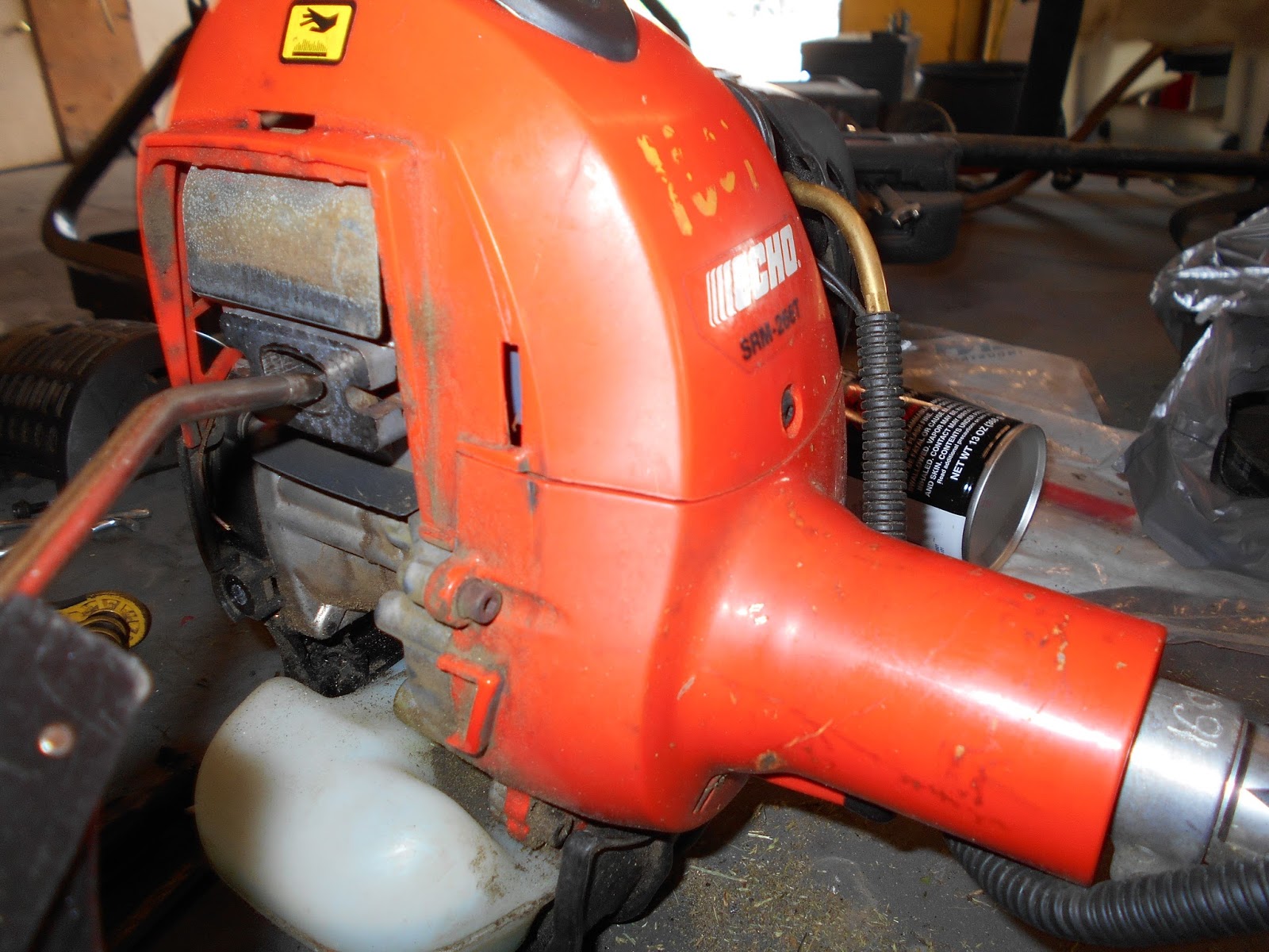
Top picture in this set of three shows you the allen head bolt that needs to be removed.  The second picture is of the muffler heat guard, which just lifts out of the way. Now in the third picture, this is the muffler.  Two 5/16ths nuts and two lockwashers  per side and the muffler will lift off. There will be a gasket behind the muffler which can be lifted out.  You might have to move (bend) a metal shield behind the muffler to get the gasket out.  The bolts slide out on either side.
It is hard to see in this picture but there is sufficient carbon build up to slow down the exhaust gases upon exiting the engine.  Remove the spark plug so that the piston moves up and down freely, and when the piston is at BOTTOM dead center (all the way down and just barely starting to return to the top)...
...I use a small battery terminal brush to clean out the carbon. Then I blow it out with compressed air as shown.
You might have to do this a couple of times to get as much carbon loosened up and blown out as possible.  The next step after this is to reinstall the spark plug, find a spot where you will not catch anything on fire, and start the engine.  be forewarned, there will be sparks flying for a couple of minutes.  This is more carbon leaving the cylinder. Run the engine at full throttle for about a minute.

Reassemble the muffler assembly reversing the steps previously outlined and test again.  You will definitely hear a difference in the engine. Tightening the muffler down will force the metal piece back into place, if necessary.

This is written for an Echo string trimmer model SRM 266T.  Other makes and models look similar but essentially all work in the same manner.